
Home -> About
Meet Feritoskop
Specifications
How about some numbers? Here you go...
Feritoskop can sample the measured signal with the frequency of 200 Hz and thus, the recommended
input signal frequency must be less than 100 Hz. Input voltage is limited to range: 0-5 V due to
Arduino input regulation. In the case of negative voltage, Feritoskop has its own protection using resistor and
two Schottky diodes.
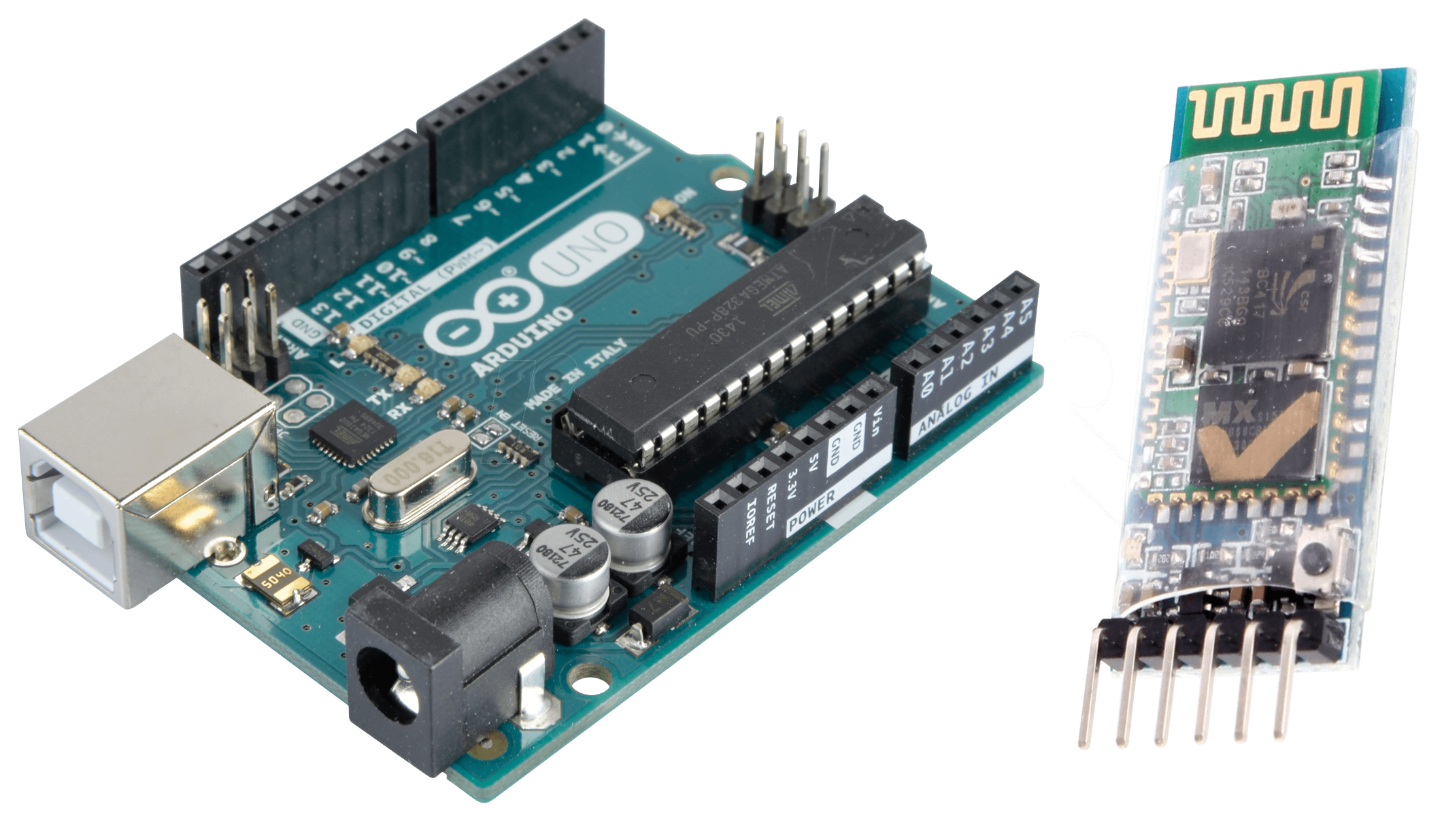
Arduino Uno microprocessor is ATmega328P and the Bluetooth module used is HC-05 with range to about 10m.
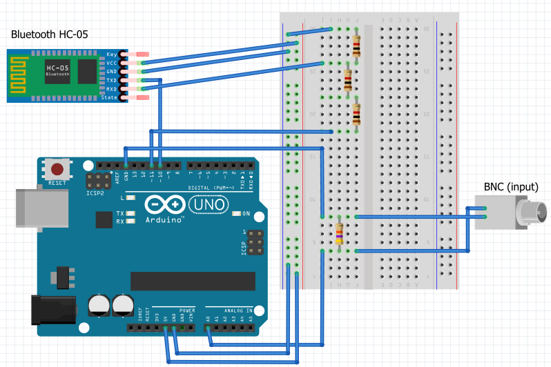
Scheme? As simple as it gets.
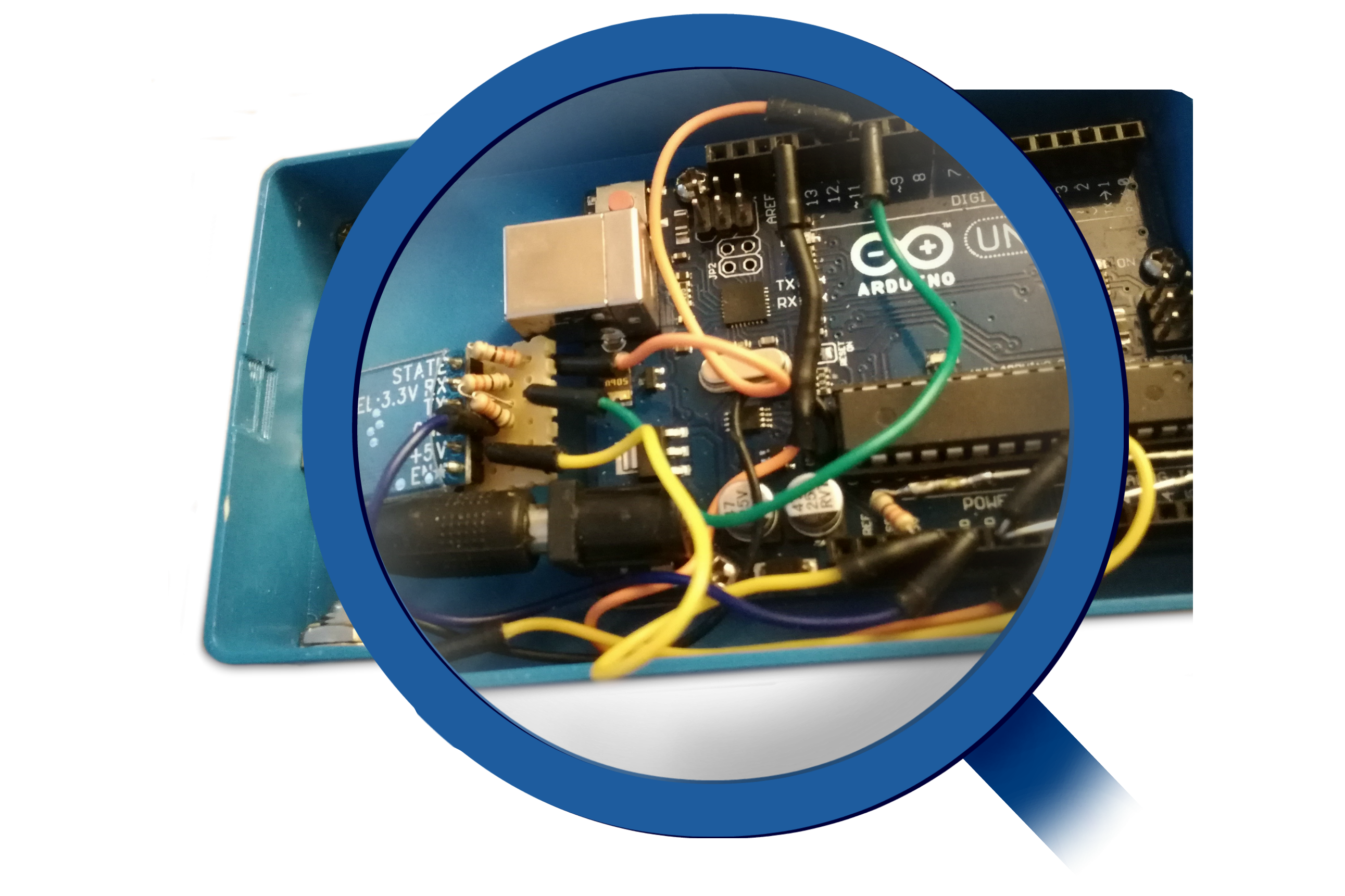
The hardware part of the project consists of Arduino Uno development boards with
ATmega328P microprocessor, power supply, switch, Bluetooth module for Arduino -> HC-05, BNC connectors,
several resistors and experimental plates and cables for connecting all parts of the device.
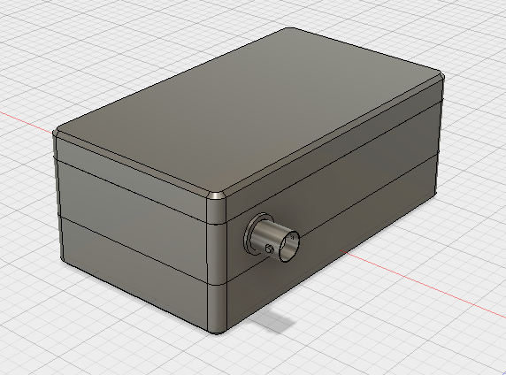
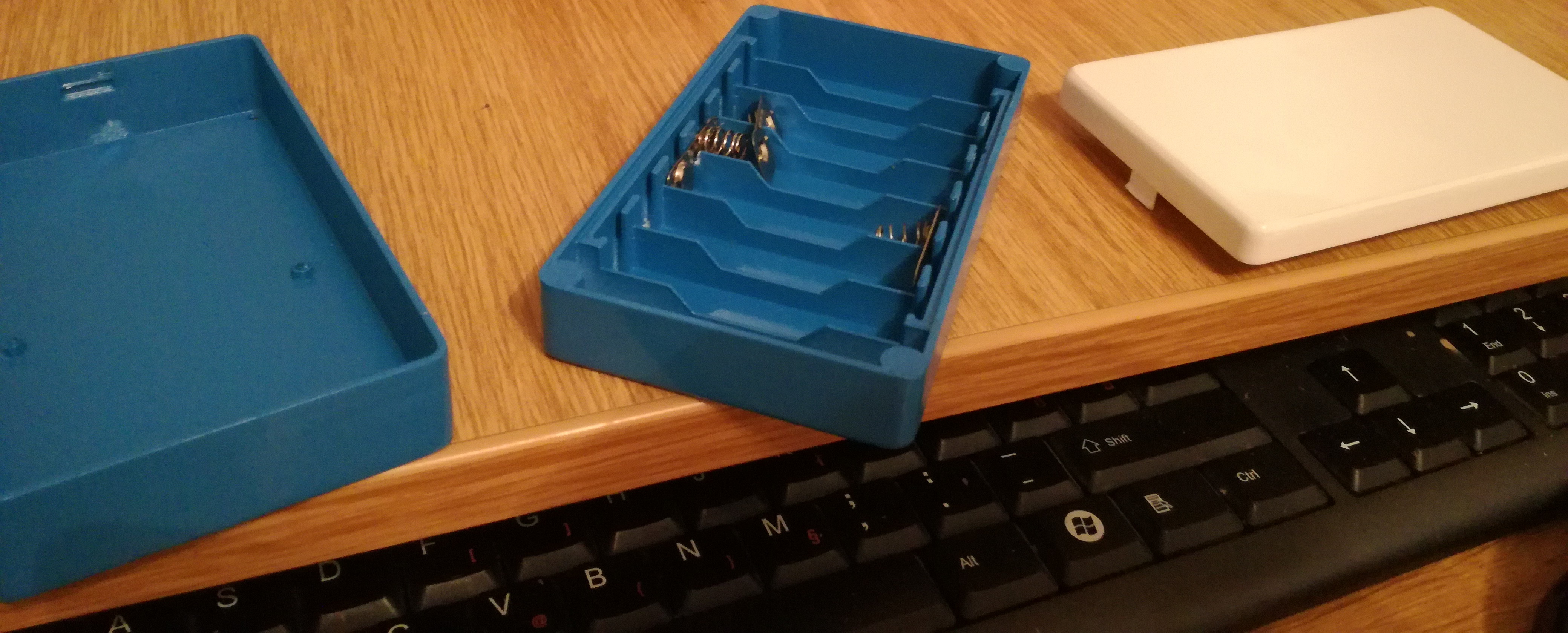
Housing? 3D printed!
The housing of the Feritoscope is a 3D-printed case model created in the
Autodesk Fusion 360 software package. The housing, corresponding to the system requirements,
consists of three parts: the lower part (power supply), the middle or main part with all electronics
and the upper part - the lid. The lower part is a power supply unit and contains the necessary elements
to accommodate 6 x Ni-Mh batteries, voltage 1.2V (± 0.03V), which are serially
connected to provide a 7.2V output voltage sufficient for powering the Arduino plate
(recommended voltage power supply: 7-12V, limit: 6-20V) and the ignition / shutdown switch.
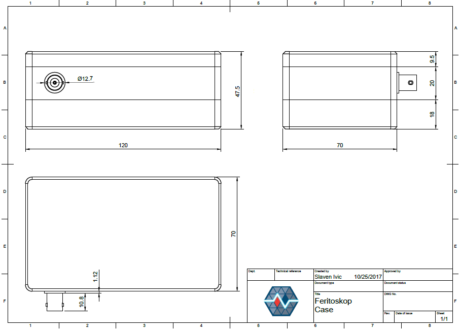
Dimensions
Feritoskop team. Who are we?

Slaven Ivić
Student at FERIT

Anamarija Blavicki
Student at FERIT

Vedran Ivić
Student at FERIT